3D Central
Train Flatcar
UPDATE: (2018-01-21) This file has been updated since the original post to add details of the truck design.
UPDATE: (2018-01-24) This file has been updated since the original post to add improved hole design for the wheel shafts in the truck design.
UPDATE: (2018-04-03) Version05.scad has been updated since the original post to add a ladder at each corner.
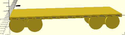
As soon as the steam engine was essentially done, and it had a display track under the wheels, it immediately became obvious that the engine needed other cars to pull. It needed to get to work. The first car which came to mind was a passenger car, but I realized that no matter which container box was involved, whether for people, animal stock, solids or liquids, every car would need an undercarriage to support the container. Therefore, a flatcar logically comes next after the engine. The flatcar can work all on its own, but it also provides support for all other car designs.
The image to the right is really just a mockup view. I will use it again and again as I design other cars, using this sketch design as visual support for the actual upper parts which will be the other cars (passenger, grain, tanker, etc.). The mockup is below the zero mark on the vertical (Z) axis and is NOT intended to be printed as-is. Its value is visual and temporary. As an example, here's a later mockup done for a tanker car with the tank parts sitting on top of the flatbed mockup to make a nice visual for descriptions like this one.
The code for the flatcar mockup is included below. I copy the code into a new car design of a new "top". It helps to make the design look more real. When it is time to print, I comment out the mockup code.

The mockup is incomplete, intentionally. It lacks lots of details. The details of the real flatcar follow below.

OpenSCAD has colors for highlighting design components, but only in previews (F5). Colors have no effect on full rendering (F6).
The color("lightblue",1.0){...} command uses a series of standard color names. It can also use red/green/blue decimal values between 0 (zero) and 1 (one) to specify other colors. The names officially are written in "CamelCase" as needed, but OpenSCAD allows the use of any case. "LightBlue" and "lightblue" are both acceptable. That is also described as "case insensitive". All the elements you want to be a particular color need to be enclosed in the curly brackets of the command. The number value in the command controls how opaque the color is. A value of 1.0 is fully opaque and is the default if you leave it out of the command. The color names and more information is available by way of the OpenSCAD Cheatsheet. (I'm using version 2015.03, the stable version on my Linux distribution.)
If you have recently looked at the web page about the steam engine, you will recall that it was put together from several individual files, printed separately, and then combined in live space. The flatcar project started out as several files, but fortunately ended up fitting into a single print file because of careful spacing of parts so that the entire set of flatcar parts could be printed all at once. It does take over five hours to print for me, but it is less work (and time) than printing several files separately.
The original set of files were divided by the colors you see above. The four wheelsets (red), the split "trucks" (light and dark blue), and the flatbed proper (green) turned out to just fit onto the Lulzbot Mini print surface if I carefully placed each part. The color option in OpenSCAD is a neat feature to allow us to highlight elements in a design while working on them or discussing them. The colors in OpenSCAD preview are just a preview. They do not control my single-extruder printer. I can handle only one color at a time. I'm planning to print all the flatcar pars in black filament. I'll need to order some more soon, I guess. Other car tops may be done in brighter colors. Paint is also an option, of course.
Split Trucks
The undercarriage of a real train car is made of two subassemblies called trucks or bogies which can rotate enough to allow a long car to go around a curve in the track. Each truck typically has two wheelsets and is mounted under the car near each end. While this train is not an accurate model of a real train car, I did want to make it theoretically possible to use curved track.
The truck used here is split into a top component with a centered hole removed and either a front or back bottom piece. The top is the same at either end of the car. The tricky bit is removing a hole in the cube, but then filling back a lip that is tighter than the overall hole. That way a peg that is part of the bottom of the truck can "latch" into the hole of the top. That means, once it is all put together, you can then pick up the whole train car, wheels and all. The peg snaps in and then doesn't fall out.
Modules of code are used extensively in this project. Modules make OpenSCAD code more compact and also help to prevent small errors from creeping in while editing duplicate sections of code. While it is not always possible, the more you can use modules, the "better" your code will be.
module top(){
    color("lightblue",1.0){
    difference(){
    cube([len,thk,ht*.667]);
    translate([len*.5,thk*.5,ht*.2])
    cylinder(ht,cyld*1.1,cyld*1.1);
    } // end diffefrence
    difference(){
            translate([len*.5,thk*.5,ht*.55])
        cylinder(ht*.12,cyld*1.1,cyld*1.1);
        translate([len*.5,thk*.5,2])
        cylinder(ht,cyld*.75,cyld);
    } // end difference
} // end color
} // end top() module
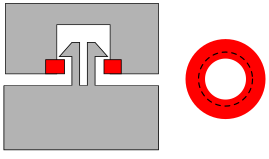
The front and rear trucks are essentially the same, cubes with a peg to stick up into the top of the truck. The peg is a modification of the one used to make the hand crank project. (Reuse is good.) It is built of two cylinders, a thin shaft and a "lip". Then the peg is split by using difference(); of a cube to make a slot in the middle of the peg. The slot allows enough flex so that the peg can slip into the upper part of the truck.
The upper part of the truck has a cylinder removed which is wide enough to accomodate the lip of the peg, but then another "layer" (shown in red) is put in to partially plug the end of the shaft, just enough to allow the flexing lip to force through but then spring back to "latch".
The front version has an extension with a pin while the rear version has a similar extension with a hole in it. The pin from one car will fit into the hole of the next...a train...not just a row of separate cars. That's the plan, anyway.
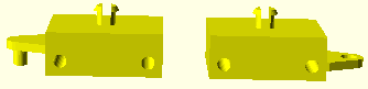
The pin and the peg, sticking out sideways as they do, need support. It would be possible to let your printer's slicer software provide its automatic support matrix, but I've found sometimes a hand-designed little pointy pin is good enough. In this next section of code, the pointy pin is a module called support();. In this case, the support module uses a function call with a sizing value passed to the module each time it gets called (used). The module uses a variable labeled "len2" and the call from the end of the truck code specified a 14mm length for the support pin.
module support(len2){
    cylinder(len2,1.5,.5);
}
module truckfront()
{    difference(){
translate([offsetx+30,0,0])
cube([40,15,thk]);
// car truck wheels shafts
translate([offsetx+35,5,0])
cylinder(35,2.3,2.3);
translate([offsetx+65,5,0]) // moved two mm forward
cylinder(35,2.3,2.3);
    }
    translate([offsetx+50,5,15])
    rotate([270,90,0])
    peg2();
    translate([offsetx+48,20,0])
    support(12);
        translate([offsetx+52,20,0])
    support(12);
// connection to next car (front)
hull(){

    translate([offsetx+20,9,15])
    rotate([90,0,0])
    cylinder(3,5,5);
translate([offsetx+30,6,6])
    cube([2,3,2]);
    translate([offsetx+30,6,22])
    cube([2,3,2]);
}
// connecting pin
translate([offsetx+20,8,15])
rotate([90,0,0])
cylinder(8,2.5,2.5);
}
// support for connector pin
translate([offsetx+17,5,0])
support(14);
Wheelsets
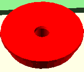
Each wheelset combines two parts, a wheel made from two cylinders for the wheel itself. One wheel has a solid cylinder for the shaft between the wheels, and the second (the offside wheel) has a hole in it to receive the shaft from the other. I have found that the upper end of the shaft flares a little bit and the hole through the other wheel melts in a bit on the heated printer bed so that I need to sand the shaft a little, and then ream the hole also to get a snug fit. After the fiddling, I can slide the shaft through one of the truck holes and then add a dab of superglue to the shaft end to solidly attach the other wheel.While the information in red in this paragraph remains true, I have found another solution: create a 1mm thick tapered cylinder removed at both the top and bottom of the shaft through the truck block and on the upper end of the hole in the wheel. This process is often called making a "chamfer" in woodworking and is also like doing a countersink for a screw. As a result, there's little or no need to ream the holes. Sanding the top of the shaft on the opposite wheel still helps.

One of the interesting facets of doing 3D printing is it similarity to writing computer code for apps or programs. An aphorism of Free Software (AKA "open source") is "release, early and often. You get to examine the code "source", not just the STL to make a print. My practice of developing projects is in keeping with the aphorism. I will try to have these web pages appear as soon as I have a "working" version of a project. I expect the notes to improve over time as the projects themselves move from version00 to later versions.
module wheelset(){
// carriage wheel
{
cylinder(5,10,10);
    translate([0,0,3])
    cylinder(1,10,12);
    translate([0,0,4])
    cylinder(1,12,12);
cylinder(42,2,2);}

// offside carriage wheel
difference(){
translate([24,0,0])
{
cylinder(5,10,10);
    translate([0,0,3])
    cylinder(1,10,12);
    translate([0,0,4])
    cylinder(1,12,12);
}
// remove to receive shaft
translate([24,0,-.1]){
cylinder(5.2,2.15,2.15);
// bottom chamfer
cylinder(.5,2.9,2.15);
// top chamfer
translate([0,0,4])
cylinder(1,2.15,2.9);
}
}
}
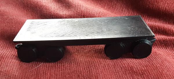
The flatbed portion of the flatcar is a simple cube the standard length and width I decided to use in this project series (145mm long, 60mm wide, and 2mm thick), close to the max length possible on the Lulzbot Mini. To enhance the look from the side, I added two hulled cubes which represent the kind of real support a long train car would require to carry any amount of weight. The little cubes shown in black on the flat slab help to align the trucks. As you can see, that means the final "top" of the flatcar is "down" during the print. It gives a smooth, flat surface for mounting any other kinds of car tops down the line.
Available Files:
flatcar02c.scad - flatcar02.stl - reaming for wheels needed
flatcar05.scad - flatcar05.stl - chamfered wheel holes (easier assembly)
GPL3 License