Checker
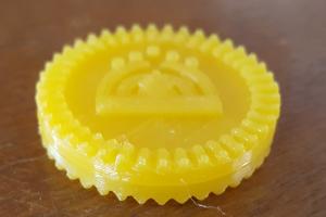
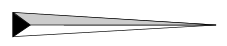
This apparently simple project turned out to be a much bigger challenge than I had expected. I started trying to make the notched edge with a cube rotated around in a circle, but could not work the spacing so that the notches matched the ridges to allow two checkers to stack together (a requirement for crowning!). By converting from a long, thin cube to a long, thin tetrahedron, the fit was eventually solved. Challenges described below kept the checker from being simple for a novice user of OpenSCAD, like me.
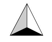
If you have not already learned about geometry, or have forgotten, a tetrahedron is a triangular pyramid. The black colored base in the image to the right is a triangle. The pyramids of Egypt have a square base instead and have five faces instead of four.
The tetrahedron is the simplest form of a polyhedron. There is no tetrahedron command. Instead, OpenSCAD uses the polyhedron command to deal with all potential numbers of faces. It is the most powerful 3D command in OpenSCAD.
With all that power comes a need to be very precise in doing the work. I rushed into the job and suffered quite a bit of confusion and frustration until I read the manual more thoroughly. If you know the rules, you'll probably spot my mistake in the following code.
module tetra()       {
polyhedron( points=[ [0,15,0],[0,20,1],[1,20,0],[-1,20,0] ],
faces=[[0,1,2],[0,1,3],[0,2,3],[1,2,3] ], convexity=10);}
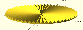
Now that you have looked, I'll try to explain. There are four points in a tetrahedron, three to define the base and one to identify the point. Once I defined each of them to make a long, thin tetrahedron, the next step was to tell OpenSCAD how the faces of the solid should be made from the available points. I did that, but made a rookie mistake. OpenSCAD wants each face to be defined by going clockwise from point to point for each face. In addition, I should be looking at the face from the "outside" of the polyhedron while going clockwise. I did not do that in the code above. I did some faces clockwise, but I did others counterclockwise. I had defined my tetrahedron, but not the right way. As a result, I got a successful first level preview (F5 - Preview) of the checker. However, when I did the second compiling step (F6 - Render) and also made an attempt to export the STL file, I got an error: WARNING: Object may not be a valid 2-manifold and may need repair!
 Preview -
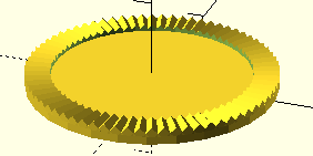
 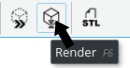 - Render
"2-manifold"? What's that?
I've read several explanations, and I'm still fuzzy about what 2-manifold means. If I can figure out a simple explanation, I'll update this page later.
Looking very closely at the compiled/rendered image, I could see that the polyhedron looked not quite solid. The preview level looked fine. The final compiled version looked incomplete/empty. I think I had described a 2-manifold geometry, but I had NOT described it with clockwise point references which are expected by OpenSCAD.
I have since joined the OpenSCAD mailing list where I could have posted the offending code so a more advanced user could help. That's a very good way to get help if you are not involved with a local makerspace with OpenSCAD users. There is also an archive/forum for the mailing list. A careful search there might also have given me my answer before sending my question to the mailinglist. (To post to the mailinglist by way of the forum, you need to join the forum separately because the archive is run on 3rd party software.)
I was a teacher for 36 years, so I am used to seeing things not work the first time. I always looked forward to helping my students analyze "failures" because failures are not a bad thing. They help us to learn. Mistakes can be fixed by looking at a problem from a new perspective or following clues given by friends, teachers, textbooks, etc. The specific example here might not have an "answer" in the manual, but my more thorough reading got me to see that I had not initially done clockwise point references for each face of the shape I wanted.
Ultimately, my early tries also needed more adjustments. I had initially used too many smaller tetrahedrons around the checker edge. It looked good in OpenSCAD, but the physical notches were too tiny to work. The final version offered here for your inspection uses a larger iteration value to count around the circle of tetrahedrons with wider notches. The top point around the perimeter is also taller. Now two checkers properly sit on one another to stay notched in place. "King me!" works.
Finally, I'd like to point out a nice feature of the slicer software, Cura, which comes with the Lulzbot Mini. I can create separate parts and then load each one into Cura, adding them to the print bed preview (as long as they fit). Then Cura lets us save the combined parts as a new STL file which contains all the parts we have loaded for later use as a combination 3D print. COOL! That saves all the work of trying to use the translate command to move all the parts around in OpenSCAD.
Note:
Before I found out out about this trick, I was loading several parts into Cura by clicking each one that I wanted while holding down the Ctrl key. That is still useful if I want to set up an impromptu print of a desired grouping of objects.
Available Files:
checker-blank.scad - for study and criticismchecker-crown.scad - for even more criticism
checker-both.stl - to print BOTH halves of the checker (sorry this file was missing before 2018-04-03)
GPL3 License